When you hear the term ‘manufacturing’, the immediate scene that comes to your mind is machining a solid block of material to the required shape using a machine and the chips are taken out as scrap.
In contrast to the above conventional process, the Additive Manufacturing (AM) process builds the three-dimensional shape by adding layers of material, one above the other. All the layers of material are bonded together to make the 3-dimensional-shape.
Page Contents
- What is Additive Manufacturing?
- How 3D Printing Works?
- Step 1: Create a 3D (Three Dimensional) Model.
- Step 2: Covert the 3D model into numerous digital slices or layers.
- Step 3: Transferring the 3D model from your computer CAD software to the computer of the 3D Printer.
- Step 4: Setting the 3D printer including loading of the material.
- Step 5: Printing the object.
- Step 6: Extract the fabricated 3D object and move it for post-process operations.
- Types of Additive Manufacturing Processes
- Pros and Cons of Additive Manufacturing
What is Additive Manufacturing?
Definition: Additive manufacturing is a process of building three-dimensional objects by adding material one layer at a time. The one-sentence explanation of Additive Manufacturing can be Additive Manufacturing is the opposite of the conventional Subtractive Manufacturing processes.
You are probably conversant with manufacturing technologies like turning, milling, grinding, etc. where the desired object is produced by machining and removing material from a solid-block of material to the required shape. You have machined the desired shape by subtracting (machining off) the excess material from the solid-block and this process is called subtractive manufacturing.
In contrast, in Additive Manufacturing (AM), you are adding or depositing the required material at the selected location in the form of numerous layers to create the three-dimensional object.
You can conceive a design in your CAD system, convert it into a three-dimensional model, and then use the AM process to replicate it into a real-life 3D-object by depositing layer-over-layer of material till the object is created.
Additive Manufacturing is a technological name for the process popularly known as 3D Printing. In fact, 3D printing is one of the more popular additive manufacturing processes, but it’s not the only one. We will discuss some of the other processes later in this guide.
How 3D Printing Works?
There are different technologies of Additive Manufacturing and you have to choose a particular technology depending on the object you want to fabricate, its material, its function, and its purpose.
However, the broad concept of Additive Manufacturing or 3D printing can be explained in the following steps.
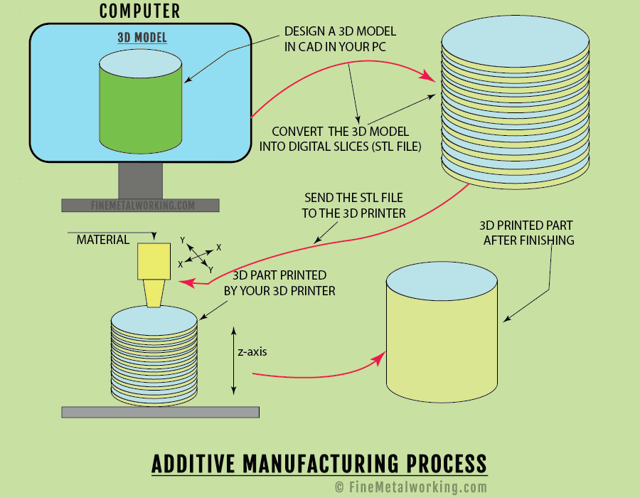
Step 1: Create a 3D (Three Dimensional) Model.
Your first step is to create a CAD (Computer-Aided Design) model of the object to be manufactured in 2D (two dimensional) and convert it into a three-dimensional model. Since the final object fabricated will be an exact replica of the three-dimensional model, you must ensure that the three-dimensional model is geometrically correct in shape, size, and accuracy.
Alternatively, you can use a 3D scanner to scan a real object and create a 3D model in your CAD system.
Even though the Additive Manufacturing process is capable of replicating the 3D models of complex and intricate geometry, there are certain design rules for every Additive Manufacturing process viz. minimum wall thickness, minimum hole diameter, minimum rib thickness, the orientation of the object, avoiding sharp corners (to minimize stress concentration), etc. which need to be followed to achieve better results. Every AM process has its limitations.
Also, if the 3D model has an overhang, a support structure may have to be considered in the design. You can remove the support structure after the object is fabricated.
Step 2: Covert the 3D model into numerous digital slices or layers.
In the second step, you have to convert or slice the 3D model digitally into numerous two-dimensional layers enabling the 3D printer to replicate the 3D model into a real-life object by depositing successive layers of the material chosen by you (the material can be in any form, viz. liquid, metal powder, metal foils, etc.).
You have to select a ‘slicing software’ like STL (standard tessellation language) file format to convert the 3D model into a number of layers. The word ‘tessellation’ means an object created by repeated layers without a gap, and the STL file digitally converts your 3D model into numerous layers, and the AM process, like SLA (stereolithography) reads the STL file to print the 3D object layer by layer.
Your 3D Printer may have its own built-in slicing software.
Step 3: Transferring the 3D model from your computer CAD software to the computer of the 3D Printer.
The next (3rd) step is to transfer the STL file (or a similar slicing file) to the computer of the 3D printer used by your AM process. Your 3D printer will have its own software and may create its own file based on the input file to add other details such as operating temperature, support structure if needed, colors, etc.
Step 4: Setting the 3D printer including loading of the material.
In the fourth step, set up the 3D printer by loading the input material, consumables, and check the setting for object orientation, level the printer platform, and any other settings required as per the 3D printer manual. You can plan to print more than one part in one setup wherever feasible (considering the size of the object and the platform).
Step 5: Printing the object.
Your next (5th) step is to switch on the 3D printer. Your 3D printer builds the 3D object layer-by-layer (one layer at a time) and the thickness of the layer can be anywhere between 0.02 MM to 0.1 mm or more (20 to 100 microns or more) depending on the material and the AM process used. The time taken for completion depends on the size of your 3D object.
Working of the 3D printer: The working principle of the 3D printer can be roughly compared with the Ink-jet printer. When you place a print command on the Ink-jet printer to print the image designed by you on your computer, the Ink-jet printer prints the image on white paper by jetting tiny dots of ink only on the required locations and this process continues till the image is printed. The printer cartridge moves in X-axis, and the paper moves in Y-axes. You have to note that the printer jets the tiny ink dots only on the required locations.
Similarly, the 3D printer prints one layer of the 3D model in two dimensions by jetting the hot viscous material only on the required locations. After the printing of each layer, the platform (on which the object is being fabricated) moves down by one layer, and the next layer is printed. This process of printing layer-upon-layer continues until the 3D model is replicated. The movement of the printer head (material nozzle) in X, and Y- axes, and the platform (up and down) in the Z-axis is controlled by the 3 D printer computer.
During this article, you will come to know about the different types of AM processes and the material used can be metal powder, liquid resin, material in the form of wire, or thin sheets. All these processes work differently, however, the basic principle as explained above will be the same.
Step 6: Extract the fabricated 3D object and move it for post-process operations.
Your next and last step is to remove the 3D printed object from the platform and move it for further operation. You may have to wait until the object is cooled before taking it out. The post-process operation depends on the AM process and may involve cleaning, hand grinding of the surfaces and painting, and in some cases post-machining, heating, or heat-treatment operations.
Types of Additive Manufacturing Processes
Although we use the term ‘3D printing’ very often in place of Additive Manufacturing, the technology of Additive Manufacturing has a wider scope than 3D printing and is a fast-growing future technology.
Additive Manufacturing is broadly categorized into 7 types of processes.
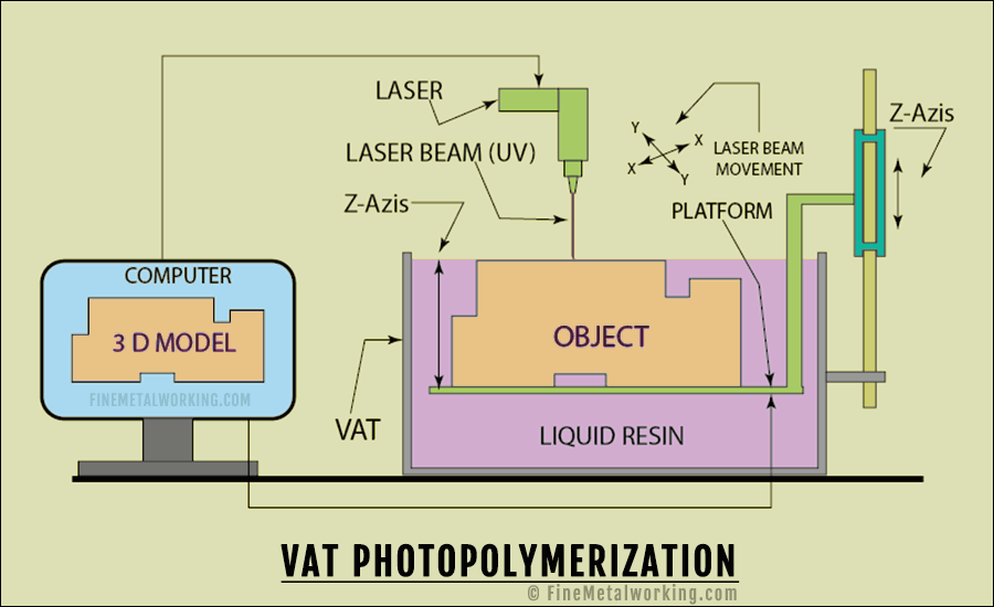
1. Vat Photopolymerization
In this process you use a photopolymer liquid resin as the raw-material that becomes solid when comes in contact with ultraviolet (UV) light and the process of photopolymer liquid resin becoming solid when exposed to UV light is called photo-polymerization and this involves a chemical process.
You can do Vat Polymerization by using two 3D printing processes, viz. SLA (stereolithography) and DLP (Digital Light Processing).
Your printer system consists of a vat containing the liquid resin and a platform (on which the object is fabricated) moves up and down on Z-axis, in the vat. Then, you have the laser nozzle which has movement in X, and Y-axes. The movement in X, Y, and Z-axes are controlled by your printer computer.
During working, the platform of your 3D printer is at the same level as the resin in the vat and the laser beam moves in X, and Y-axes to selectively expose the resin to laser (UV light) and only the exposed portion of the resin layer becomes solid.
The platform will move down by one layer in Z-axis and brings a fresh layer of resin to the contact of the laser beam.
This process of the platform moving down and bringing a fresh layer of resin to the exposure of the laser beam continues until the 3D model is replicated into a real-life object. After the completion, you can drain the resin and take out the object.
Many times, support structures are designed as a part of the 3D model to support overhanging portions and this support structure is removed after the printing is completed.
Your printer may have a blade that passes over every completed layer to ensure there are no defects in the resin for the processing of the next layer.
Post-processing of 3D printed parts: You can clean the excess resin from the object and then rinsing in alcohol and water. You can remove the support structure with a sharp knife, then do scrubbing, sandpapering, etc. to get the final finish. You may also use UV light for further curing.
Advantages:
- Maximum size of the component-1 M × 0.8 M × 0.5 M (200 Kg.)
- Good accuracy and surface finish and
- The process is comparatively fast.
Disadvantages:
- Limited type of materials
- High cost and more time on post-processing work and
- Require support structures.
2. Material Jetting
The Material Jetting printer system has a printer head & UV light which moves in X, and Y-axes, and a platform (on which the object is fabricated) moving up and down in Z-axis. The movements in X, Y, and Z-axes are controlled by the computer.
Material jetting works similar to the Inkjet printer, however, this printer-head selectively sprays (jets) the liquid photopolymer in the form of tiny droplets, followed by a UV light to harden it. The jetting of the material can either be continuous or as per requirement or demand (on demand) for creating the required objects.
After the first layer is printed, the platform moves down by one layer thickness, ready for the deposition of the next layer and this continues till the complete fabrication of the object. The approximate thickness of each layer is 0.016 mm (16 microns).
The material jetting process can do multi-material printing in multi colors, however, the 3D model may have to be modified into a number of sections depending on the number of materials and colors required. The material jetting process of the printer uses a thermal or piezoelectric method to convert the raw-material (polymers and plastics) into liquid.
Materials used: High-density polyethylene (HDPE), Polypropylene, Polystyrene (PS), Polymethyl methacrylate (PMMA), or acrylic, Acrylonitrile butadiene styrene (ABS), Polycarbonate (PC), and High impact Polystyrene Sheet (HIPS).
Post-process operations: The support structures are built using a material dissolvable in water or sodium hydroxide and hence you can easily remove it without any mark on the object. The aesthetic and other details are taken care of during the printing stage, hence you have limited scope improving the aesthetics.
Advantages:
- High accuracy combined with low material wastage and
- You can build objects in multi-material and multi-colors.
Disadvantages:
- Support structures are required and
- Limitation of materials used.
Types of Material Jetting (MJ): You have three different types of Material Jetting processes viz. Poly jet, Nano-particle Jetting, and Drop on Demand (DOD), however, the basic principle or technology is the same.
Poly Jet Process:
In this process, the printer selectively jets a micro-thin layer of photopolymer material onto the platform and the layer is immediately cured (solidified) by the UV light. The platform moves down by one layer, the next layer is printed, and this process continues until the object is completely fabricated. The approximate layer thickness is 0.014 mm (14 microns).
Support structures are built using gel-type material and you can remove the support structures by a water jet during the post-processing. You can use multi-materials.
Nanoparticle jetting (NPJ)
The NPJ process uses cartridges containing solid metal nanoparticles suspended in a liquid. Separate sealed cartridges containing build material and support material are loaded into the printer.
The system of the NPJ consists of two print-heads (one for build material and one for support material), and they, with their thousands of nozzles, jet very fine droplets of both (build and support) materials simultaneously to form a layer on the building tray or platform.
The building tray of the NPJ is maintained at a high temperature (300º C) and immediately evaporates the liquid, leaving behind the solid Nanoparticles of the build and support materials on the layer. This process of jetting of the next layer and evaporation of its liquid continuous until the object is completely fabricated.
Materials like stainless steel and ceramic are used as build materials in NPJ.
Advantages:
- Less health hazard and easy handling since the build and support materials are loaded in sealed cartridges
- Nanoparticles and the very thin (25 microns) layer gives high accuracy and a smooth surface even when the shape is intricate
- Separate and easily removable build material helps in designing complex and intricate shapes with thin walls and sharp edges.
Drop on Demand (DOD)
The DOD 3D Printer consists of a platform with up and down movement in Z-axis, two print-heads with the cartridge, one each for build material, and support material, and cutter-head assembly. The platform can move up and down in Z-axis and the print-heads have movement in X, and Y-axes and the movements are controlled by the computer.
The Drop On Demand process uses viscous fluid materials, and deposit tiny dots only as required (on demand) and not continuously as in other printers. The typical use of the DOD process is for creating wax patterns for investment castings, specifically in the Jewelry industry.
The wax material is loaded into the printer-head in powder form and then melted into a viscous liquid in a hot tank.
The DOD process builds the object by the deposition of layer-by-layer of build and support material and every layer is milled to make it flat and uniform before the next layer is deposited. You can dissolve the support material in a liquid, and the clean wax pattern is ready for use.
Advantages of Material Jetting:
- High level of accuracy
- Due to thin layer-by-layer construction, this process gives out parts with smooth surface comparable with injection molding and high dimensional accuracy
- Low wastage of material due to accurate jetting of material (iv) Multi-material and multi-color printing is possible without scarifying the printing efficiency
- Material jetting give homogeneous mechanical and thermal properties and (vi) NPJ and DOD process components are better in mechanical properties than Poly-jet process components.
Disadvantages:
- Material jetting components have poor mechanical properties and not suitable for functional use
- Material properties of photosensitive material used in poly-jet gets deteriorated fast
- The components are brittle and cannot take the load
- Very limited choice of material and
- Even though support materials are easy to remove, it adds to cost and time.
3. Binder Jetting:
The Binder Jetting uses a powder-based material (granular form) and a binder to create the 3D object. The printer system consists of a platform that moves in Z-axis (up and down) and a print head moves in X, and Y-axes. The movements in the X, Y, and Z- axes are controlled by the system computer.
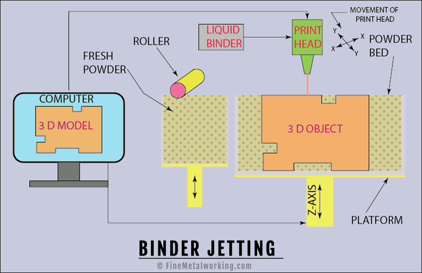
A layer of powder material is spread over the platform of your printer and the printer head moves in X, and Y- axes to selectively deposit the binder on the layer of powder material. The layer thickness can be 0.091 to 0.201 mm (91 to 201 microns).
The platform moves down by one layer thickness and another layer of powder is rolled over the previous layer. Again, the print head of the printer moves in X, and Y- axes and selectively bonds the powder layer. This process continues until the complete object is fabricated.
The printer fabricates the final object by bonding the metal powder wherever the print-head had deposited the binder.
The object is self-supported on the metal powder bed and you can remove the object from the powder bed once the process is completed.
This technology is often referred to as 3DP and has copyright under this name.
You can use the binder jetting for color printing and materials like metal, polymers, and ceramic can be used. Many combinations of build and binder material are possible.
One of the typical applications of binder jetting is to make a mold for sand casting.
You may need post-process operations to increase the mechanical properties of the bonding material.
Materials used in binder jetting: Stainless steel, Glass, ABS, PA, PC, Ceramics
Advantages of Binder Jetting:
- You can make objects with different colors
- Wide variety of materials to work, viz. metal, ceramics, and polymers
- Faster than other 3D printers and
- Possibility of different binder and powder combinations and mechanical properties.
Disadvantages:
- Limitations of suitability for structural or functional use due to the binder material and
- Post-processing operations increase the total time of completion.
Depending on the type of powder and the process used, the binding material can be Furan Binder, Silicate Binder, Phenolic Binder, or Aqua-based Binder.
4. Material Extrusion:
The Material Extrusion system consists of an extrusion nozzle moving in X, and Y- axes and the platform moves up and down on Z-axis. The movement in X, Y, and Z-axes are controlled by the system computer. You can feed the raw material to the extrusion nozzle in the form of a wire.
The raw material fed to the printer is heated to the molten state and the extrusion nozzle selectively deposits a layer of the molten material by moving in X and Y axes. The platform moves down by one layer, and the printer nozzle deposits the next layer over the previous one. Since the material is in a molten state, the two layers get fused together. This process continues until the object is completely fabricated. The layer thickness can be 0.180 to 0.340 mm (180 to 340 microns).
The above is the most common technique adopted by low-cost 3D Printers used by hobbyists and others. This process is registered as a trademark in the name Fused Deposition Modelling (FDM).
Fused Filament Fabrication (FFF) is the other 3D printing process under this category.
The FDM process is similar to any other 3D Printers and builds the object layer-by-layer, however, the difference is that the material is added in a continuous stream at constant pressure and the accuracy of the process depends on the maintenance of the continuous stream of material under steady pressure.
Material used: Polymers and plastics viz. ABS, Nylon, etc.
Advantages of Material Extrusion
- Popular and low-cost process with wider material selection
- Process is easy to understand
- ABS is easily available and gives good structural properties to the components and
- Initial cost and running cost is low and affordable.
Disadvantages:
- Shrinkage happens due to the use of molten material and has to be provided for
- Low accuracy compared with other 3D printers and accuracy depends on nozzle size
- Maintaining the material flow under a steady pressure is important for the component quality
- The layer lines are visible and some materials can be toxic
- The component strength is weak in the vertical direction (Z-axis) and
- Risk of warpage.
5. Powder Bed Fusion
The Powder Bed Fusion (PBF) system consists of a platform that moves up and down (Z-axis), and a heat source (laser, electron beam, or plasma) moving in X, and Y- axes. The movement in X, Y, and Z- axes are controlled by the 3D printer computer.
The system of the PBF system has the arrangement to spread the powder material in a layer form from its source (a hopper or tank filled with metal powder and located near the platform), and a roller or blade to spread the powder layer one after another.
The platform and the layer of powder where the melting /sintering happens in the PBF process may be placed in an inert atmosphere filled with inert gas to protect the object from corroding /oxidation.
The process in the PBF begins with the roller spreading a layer of powder material on the platform, and the heat source moves in the X, and Y-axis to selectively melt and fuse the powder material. The platform of the PBF moves down by one layer thickness, the roller lays the next layer of powder material and this process continues till the object is completely fabricated. The approximate layer thickness can be 85 to 140 microns.
Common printing techniques of the Powder Bed Fusion system are,
- EBM (Electron Beam Melting)
- DMLS (Direct Laser Metal Sintering)
- SLS (Selective Laser Sintering)
- SLM (selective Laser Melting) and
- SHS (Selective Heat Sintering).
The Electron Beam Melting (EBM) process is a Powder Bed Fusion technology where an electron beam is used to selectively melt and fuse the layers of metal powder and is best suited for the manufacturing of dense and lightweight parts; this technology is predominantly used in aerospace, medical (customized medical implants and orthopedic application) and defense-related industries.
The electron beams of the EBM are powerful compared to a laser beam and hence EBM is faster than the process using a laser. However, parts processed by EBM are less accurate compared to a laser beam since the layer of material in EBM is thicker than the layer of material in the Laser beam. EBM processed parts require post-processing operations to improve the surface finish.
A limited range of metal powders are used in the EBM process viz. steel, nickel alloy, titanium alloys, and cobalt chrome, and all these material have high strength, corrosion resistance, and other properties important for a functional part. The material used in EBM must be electrically conductive.
The Direct Metal Laser Sintering (DMLS) and Selective Laser Melting (SLM) uses the basic technology of Powder Bed Fusion (PBF) and the heat source is a laser beam.
DMLS and SLM differ in the temperature used to fuse the metal powder and also, the metal powders used.
SLM process heats the metal powder till it becomes molten and is best suited for pure metals.
DMLS process heats the metal powder just sufficient for their sintering and is suited for working with metal alloys.
Selective Heat Sintering (SHS) is another type of PBF process where a thermal print head is used for sintering thermoplastic powder for the construction of the 3D part.
Selective Laser Sintering (SLS) is yet another process that uses the PBF technology and differs from the other PBF processes in the material powder used. The material used in SLS are thermoplastics like nylon, Polyether Block Amide (PEBA), Alumide (aluminum-filled polyamide), etc. SLS process is used for architecture models, functional parts, prototypes, consumer parts, and medical applications.
Materials used in PBF:
DMLS, and SLM: Stainless Steel, Aluminum, mild steel, Cobalt chrome, etc.
EBM: Stainless Steel, Cobalt Chrome, Aluminum, Titanium, Copper, etc.
SHS and SLS: Thermoplastics.
Advantages of Powder Bed Fusion
- Equipment are relatively inexpensive and are suitable for models and prototypes
- No separate support structures needed since powder acts as the support, however for more accuracy, a build plate is used as the support
- The used powder is generally recycled
- Wide range of materials and
- More than one part can be produced simultaneously and the number of parts depends on the part size and the build platform area.
Disadvantages
- High electricity cost
- Surface finish depends on the grain size of the metallic powder and
- There can be shrinkage in the finished part, to be taken care of during design (specifically for thermoplastics).
6. Sheet Lamination:
Sheet Lamination is a procedure of stacking and laminating of very thin sheets of material and the method of lamination can be bonding with adhesive, ultrasonic welding, etc. and the final object is made by laser/knife cutting (during the process) or CNC machining (after the process).
The two additive manufacturing technologies that utilize the sheet lamination are,
- Ultrasonic Additive Manufacturing (UAM) and
- Laminated Object Manufacturing (LOM).
The UAM process uses a layer-on-layer of metal sheets that are bound together by ultrasonic welding. The material sheet thickness can be as less as 0.15 mm and width as per requirement. Different materials like aluminum, copper, stainless steel, titanium, or a combination of two materials can be bonded together by ultrasonic welding. This is a low-energy (and low temperature) process and uses a combination of ultrasonic frequency and pressure.
Your Ultrasonic Additive Manufacturing process is a combination of Additive Manufacturing and Subtractive Manufacturing since, after the sheet lamination process, the required component is completed by CNC machining.
The LOM process follows the layer-by-layer approach but uses paper or plastic-coated paper as material and an adhesive to bond the layers of paper.
The first layer of material (paper) is placed on the platform and with the application of adhesive, the layer is bonded with the next layer. The layer thickness can be 100 to 180 microns.
The object is completed by cutting it to the required shape by moving the laser or a knife in X, and Y- axes.
It is possible to cut every layer of paper before bonding it with the adhesive.
The setup for the LOM process is relatively simple and the material used (paper) is cheap and easily available.
Advantages of LOM
Low cost, and fast process, but the strength depends on the adhesive used.
Disadvantages of LOM
- Limited material
- Finish achieved may vary depending on the paper or plastic material used and may need post-processing finishing.
You can subdivide the Sheet Lamination Process either by the material used for building the object, viz. paper, plastic, metal, etc. or by the forming methods, viz. knife cutting, laser cutting, or CNC machining. Another way is based on the laminating process, adhesive bonding, and ultrasonic welding.
The Sheet Lamination process is subdivided into
- Laminated Object Manufacturing (LOM)
- Selective Lamination Composite Object Manufacturing (SLCOM)
- Plastic Sheet Lamination (PSL)
- Computer-Aided Manufacturing of Laminated Engineering Materials (CAM-LEM)
- Selective Deposition Lamination (SDL)
- Composite Based Additive Manufacturing (CBAM) and
- Ultrasonic Additive Manufacturing (UAM).
In the SDL and UAM process, the layers of material are bonded (welded) together and then cut or CNC machined to the required three-dimensional object.
In the CAM-LEM process, you can cut the layers to the required two-dimensional shape before binding them together and the process continues till the object is fabricated.
7. Directed Energy Deposition
The DED process consists of a Nozzle-head which can move in multi-axes and selectively deposit the molten material on the platform or on the object to be repaired. The build platform has up and down movement on Z-axis. The movement of the nozzle-head and platform is controlled by the machine computer.
You may feel that this process is similar to Material Extrusion, however, there are two differences (i) the nozzle can move in more than 2-axes (4 or 5), and (ii) the material is melted by a laser or electron beam on deposition.
Even though this process can be used with polymers or ceramic, it is normally used with metal in powder or wire form.
The main application of this process is for the repair and maintenance of functional or structural parts.
Metals used: Cobalt chrome, titanium, etc.
The DED process is also called by other terms, viz. direct metal deposition, 3D laser cladding, etc.
The Direct Energy Disposition process technology can be subdivided into categories based on the energy source used to melt the material, viz. Laser-based DED-Laser Engineered Net Shaping (LENS), Electron Beam-based DED- Electron Beam Additive Manufacturing (EBAM), and Plasma or electric-based DED- Wire Arc Additive Manufacturing (WAAM).
Another subdivision can be based on the material used:
Powder-based DED system: The powder is fed through the nozzle and melted by a laser or electron beam.
Wire-based DED System: The wire is fed through a nozzle and is melted using an electron beam or plasma arc.
The DED process happens in a hermetically sealed chamber filled with inert gas or vacuum depending on the heat source used and this is done to stop oxidation of metal, specifically titanium which is a highly reactive material.
Any metal which can be welded can be used for the DED process; common metals used in the DED process are Titanium and Titanium alloys, Stainless steel, Aluminum alloys, Zina alloy, Copper Nickel alloys, etc.
DED process is used in marine, aerospace, manufacturing aircraft frames, etc.
Advantages of DED process
- Higher deposition rate of material compared to other AM processes
- DED created parts are dense and strong, and have good mechanical properties
- High-quality repair work since the grain structure can be controlled.
- Ability to do deposition of metal layers on existing parts
- Capability of building large size parts
- The material can be changed with ease and
- Low material wastage since the material is deposited only as per requirement
Disadvantages of DED
- High initial cost of the machine
- Parts produced by the DED process do not have good surface finish due to lower resolution and will require secondary operations and
- Objects cannot have support structures during construction and overhang features are not possible.
Pros and Cons of Additive Manufacturing
Following are some of the main advantages and drawbacks of additive manufacturing at its present state.
Advantages of Additive Manufacturing
- Additive Manufacturing gives complete freedom to you for designing. Design any shape with hollowness, geometric complexity, and intricacy and there will be an AM process to print it. Parts that you feel impossible to manufacture by conventional manufacturing are possible in the AM process.
- You can design a part to replace the assembly of 2 or more parts.
- In contrast to subtractive manufacturing, there is nil or minimum wastage of material in the AM process and hence it is environmentally friendly.
- The AM process drastically reduces the lead time for prototype manufacturing. You can visualize a part or a design, convert it into a geometrically correct 3D model and print the real-life part, it is almost as simple as this. With the developments in Additive Manufacturing Technology, the quality and mechanical strength of parts built by the AM process can be nearly as good as that of the conventional process. And if you need to make changes, you can always do and print a new part. This makes the development of a new product faster than anyone imagined.
- You can design parts with lightweight without sacrificing the quality or strength and this feature is very beneficial to the aerospace industry and also the automotive industry.
- Your AM process brings down the cost of manufacturing since the material wastage is nil or minimum.
- Application of the AM process is growing every day and presently it is used for producing artificial limbs for helping accident victims and also parts like stents etc. used in surgery.
- For the manufacture of the same part, the AM process consumes comparatively less energy than the conventional process of manufacturing.
- You do not need any special tooling for the AM process.
Disadvantages
- Presently the equipment for the AM process, specifically those used for metallic parts is costly and may not be affordable to many.
- The AM process is good for the development of a prototype and R & D purposes, however, at the production stage, it may work out costlier than conventional processes.
- The AM process needs raw materials specially developed for it and you have to purchase them from the proprietary source (3D printer manufacturers), hence the choice of raw material is limited.
- Most of the parts produced in the AM process may need post-processing. While the large size and metallic parts need heat treatment and even CNC machining, small parts may require scrubbing, sanding, painting, etc. and all these will increase the lead time of manufacturing.
- The AM process builds the parts by layer-by-layer and the strength of the part entirely depends on the bonding between the layers. The parts are generally weak in the direction in which the layers are built.
- The parts manufactured by the AM process, specifically, thermoplastics, are susceptible to shrinkage and has to be provided for during the design stage.
- The surface finish and texture obtained in the AM process are inferior to the conventional process and need additional operations to improve it.
Future of Additive Manufacturing
Additive Manufacturing technology has huge growth potential and it can be the technology of the future. With the development of new 3D printing technologies, new materials, and new applications, Additive Manufacturing technology has the potential to replace most of the conventional processes in the coming days.
Additive ManufacturingGlossary
List of Abbreviations you come across in the Additive manufacturing process.
| AM | Additive Manufacturing | SLM | Selective Laser Melting |
| UV | Ultraviolet | SHS | Selective Heat Sintering |
| SLA | Steriolethography | SL | Sheet Lamination |
| DLP | Digital Light Processing | UAM | Ultrasonic Additive Manufacturing |
| MJ | Material Jetting | LOM | Laminated Object Manufacturing |
| PJ | Poly Jet | SLCOM | Selective Lamination Composite Object Manufacturing |
| NPJ | Nano Particle Jetting | PSL | Plastic Sheet Lamination |
| DOD | Drop On Demand | CAM-LEM | Computer-Aided Manufacturing of Laminated Engineering Materials. |
| BJ | Binder Jetting | SDL | Selective Deposition Lamination |
| FDM | Fuse Deposition Modelling | CBAM | Composite Based Additive Manufacturing |
| FFF | Fused Filament Fabrication | DED | Direct Energy Deposition |
| PBF | Powder Bed Fusion | DMD | Direct Metal Deposition |
| EBM | Electron Beam Melting | LENS | Laser Engineered Net Shaping |
| DMLS | Direct Laser Metal Sintering | EBAM | Electron Beam Additive Manufacturing |
| SLS | Selective Laser Sintering | WAAM | Wire Arc Additive Manufacturing |